Checklist: Verifying Electrical Power Requirements for New Sewing Lines
A new sewing line requires a verified electrical setup that matches machine amperage, grounding standards, and facility capacity. This guide outlines the audit steps engineers and importers need to prevent trips, overheating, and installation failures during garment factory installation.
- Match the total amperage of every sewing machine to the facility's main service capacity before installation.
- Verify grounding and neutral separation to protect sensitive electronics and operator safety.
- Use a dedicated circuit for high-draw equipment like cutting tables and pressing stations.
- Keep a written electrical load calculation for future upgrades and compliance audits.
- Inspect cable routing and junction boxes for mechanical damage and heat buildup.
Define the Total Load Before Wiring
The first step in any sewing line electrical setup is a complete inventory of equipment. List every machine, from lockstitchers to overlockers, and note the nameplate current draw for each unit. Include auxiliary equipment such as cutting tables, pressing stations, vacuum systems, and air compressors. These items often draw power simultaneously, which increases the total demand on the service.
Do not assume that standard outlet capacity is sufficient for a full line. A single industrial sewing machine may draw less power than a household appliance, but a line of twenty machines running together creates a continuous load that strains a single circuit. The calculation must account for the duty cycle. If machines run at full speed for eight hours, the load is continuous. If they run intermittently, the calculation changes.
The final number determines the amperage required for the main breaker and the size of the feeder cable. An undersized circuit causes voltage drops, which slow down motor performance and can overheat the wiring. An oversized circuit protects the equipment but may mask a deeper facility issue. The calculation must be done by a qualified electrical engineer or the facility electrician. It is a core part of the garment factory installation process.
Check the Facility Service Capacity
The service entrance to the building sets the limit for all connected loads. Review the main breaker rating and the utility service agreement. If the facility was built for light commercial use, the service may be too small for a heavy sewing operation. The utility may require an upgrade or a new transformer.
Inspect the main switchboard for signs of overload. Discoloration on the bus bars, loose connections, or frequent breaker trips indicate the system is already near its limit. Adding a new sewing line to an overloaded panel creates a fire risk and unreliable power delivery.
If the utility service is insufficient, the options are limited. You can request a service upgrade, which takes time and costs money. You can install a generator as a backup, but this is not a permanent solution for continuous operation. In some cases, a new substation is required. This is a major capital expenditure. The electrical load calculation must happen before the machines are shipped to the site. Receiving equipment that cannot be powered is a costly and disruptive situation.
Verify Grounding and Neutral Separation
Industrial sewing machines use electric motors and electronic controls. Poor grounding leads to erratic behavior, static discharge, and safety hazards. The grounding system must be continuous from the service panel to every machine.
Check the grounding conductor size. It must match the phase conductor size per local code. A thin ground wire will trip the breaker during a fault and leave the machine ungrounded during normal operation. This creates a shock risk for the operator.
Separate the neutral and ground paths. In a three-wire system, the neutral carries current, while the ground is for fault current only. Mixing these paths causes voltage imbalance, which can damage electronic components in the sewing machine. This is a common mistake in older factories that have been modified over time.
Test the grounding resistance. A multimeter or clamp meter can verify the connection. A reading above the local code limit indicates a poor connection. Fix this before connecting the first machine. A bad ground is a red flag that the entire wiring run needs inspection.
Inspect Cable Routing and Junction Boxes
The path of the power cable from the panel to the sewing machines is a high-risk area. Cables routed through high-traffic zones get pinched, cut, or damaged. Junction boxes exposed to heat, oil, or water become failure points.
Inspect the cable routing for mechanical stress. Cables should be supported by conduit or trays, not draped over beams or pulled across the floor. A cable that is bent too sharply loses insulation integrity. A cable that is pulled tight by a moving machine will eventually break.
Check the junction boxes. They must be rated for the environment. A box with a cracked cover or rusted lid will let moisture in. Moisture causes short circuits and corrosion. In a sewing factory, lint and dust accumulate on surfaces. If it gets into a junction box, it can ignite under heat.
Use a thermal camera to scan the junction boxes and connection points during a trial run. Hot spots indicate loose connections or overloading. A connection that is too tight or too loose will heat up. This heat weakens the insulation and creates a fire risk. Fix any hot spots before the line goes into full production.
Review the Control Panel and Protection Devices
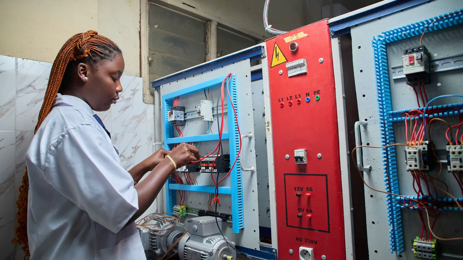
The control panel houses the breakers, contactors, and relays that protect the machines. Each machine should have its own circuit breaker or fuse. A single breaker for multiple machines creates a single point of failure. If one machine shorts, the entire line shuts down.
Check the breaker rating. It should be sized to protect the cable, not just the machine. A breaker that is too large will not trip during an overload, allowing the cable to overheat. A breaker that is too small will trip during normal operation, causing downtime.
Inspect the contactors. They switch the power to the machine. Worn contacts cause arcing, which heats the terminals and degrades the contactor. Clean or replace contactors that show pitting or discoloration.
The panel should have a clear labeling system. Each breaker must be labeled with the machine it protects. This helps the electrician during troubleshooting and reduces the time to isolate a fault. A poorly labeled panel is a red flag for poor maintenance.
Plan for Future Upgrades and Load Changes
A sewing line is not static. New machines are added. Old machines are replaced. The electrical load calculation must allow for growth. Leave 20 to 30 percent headroom in the main service and the feeder cable. This headroom covers the addition of new equipment without requiring a full rewiring.
Document the current load. Keep a written record of every circuit, its rating, and the machines connected to it. This document is critical for future upgrades and for compliance audits. It also helps the electrician understand the system when troubleshooting.
Plan for peak demand. Some factories run double shifts. The electrical load changes when the second shift starts. The service must handle the combined load of both shifts. If the service is sized for one shift, the second shift will cause voltage drops and breaker trips.
The sewing line electrical setup is a permanent part of the facility. It must be designed for the life of the installation, not just the first year. A well-planned setup reduces downtime, protects the equipment, and ensures a safe work environment. The cost of a proper electrical audit is small compared to the cost of a fire or a machine failure.
Common Red Flags During Installation
- The main breaker trips when the machines start up.
- The voltage at the machine drops below the rated level during operation.
- The cables are hot to the touch after a short run.
- The grounding wire is thin or disconnected.
- The junction boxes are open, cracked, or full of lint.
- The control panel breakers are not labeled.
- The utility service agreement does not match the required load.
- The electrician uses standard household wiring for industrial loads.
- The neutral and ground are connected at multiple points.
- The cables are routed across the floor without protection.
Each of these flags indicates a problem that must be fixed before the line goes into production. Ignoring them leads to downtime, equipment damage, and safety risks. The sewing line electrical setup is not just about turning on the power. It is about creating a reliable, safe, and sustainable infrastructure for the factory.
Final Audit Checklist
- Verify the utility service capacity matches the total calculated load.
- Confirm the main breaker rating is sufficient for the facility load.
- Check the grounding conductor size and continuity.
- Test the grounding resistance at each machine.
- Inspect the cable routing for mechanical damage and heat buildup.
- Check the junction boxes for moisture, lint, and loose connections.
- Verify the control panel breaker ratings match the cable sizes.
- Confirm the neutral and ground paths are separated.
- Label all circuits in the control panel.
- Keep a written record of the electrical load calculation.
- Test the voltage at the machine during a trial run.
- Inspect the contactors for wear and pitting.
- Ensure the cables are supported by conduit or trays.
- Check the utility service agreement for any restrictions.
- Plan for future upgrades with 20 to 30 percent headroom.
Frequently asked questions
How do I calculate the total load for a sewing line?
Add the nameplate current draw of every machine and auxiliary equipment. Multiply by the duty cycle if the machines run intermittently. The result is the total amperage required for the circuit.
Can I use a standard 15 amp outlet for a sewing machine?
A standard 15 amp outlet is insufficient for most industrial sewing machines. Use a dedicated circuit with a breaker rated for the machine's current draw and the cable size.
What is the risk of a bad ground connection?
A bad ground connection creates a shock hazard and can damage electronic components. It can also cause erratic machine behavior and reduce the effectiveness of the protection devices.
Do I need a thermal camera for the electrical audit?
A thermal camera is a useful tool for detecting hot spots during a trial run. It can identify loose connections and overloading that are not visible to the eye.
How much headroom should I plan for future upgrades?
Plan for 20 to 30 percent headroom in the main service and the feeder cable. This allows for the addition of new equipment without requiring a full rewiring.