How-To: Calibrating Vision Systems for Defects
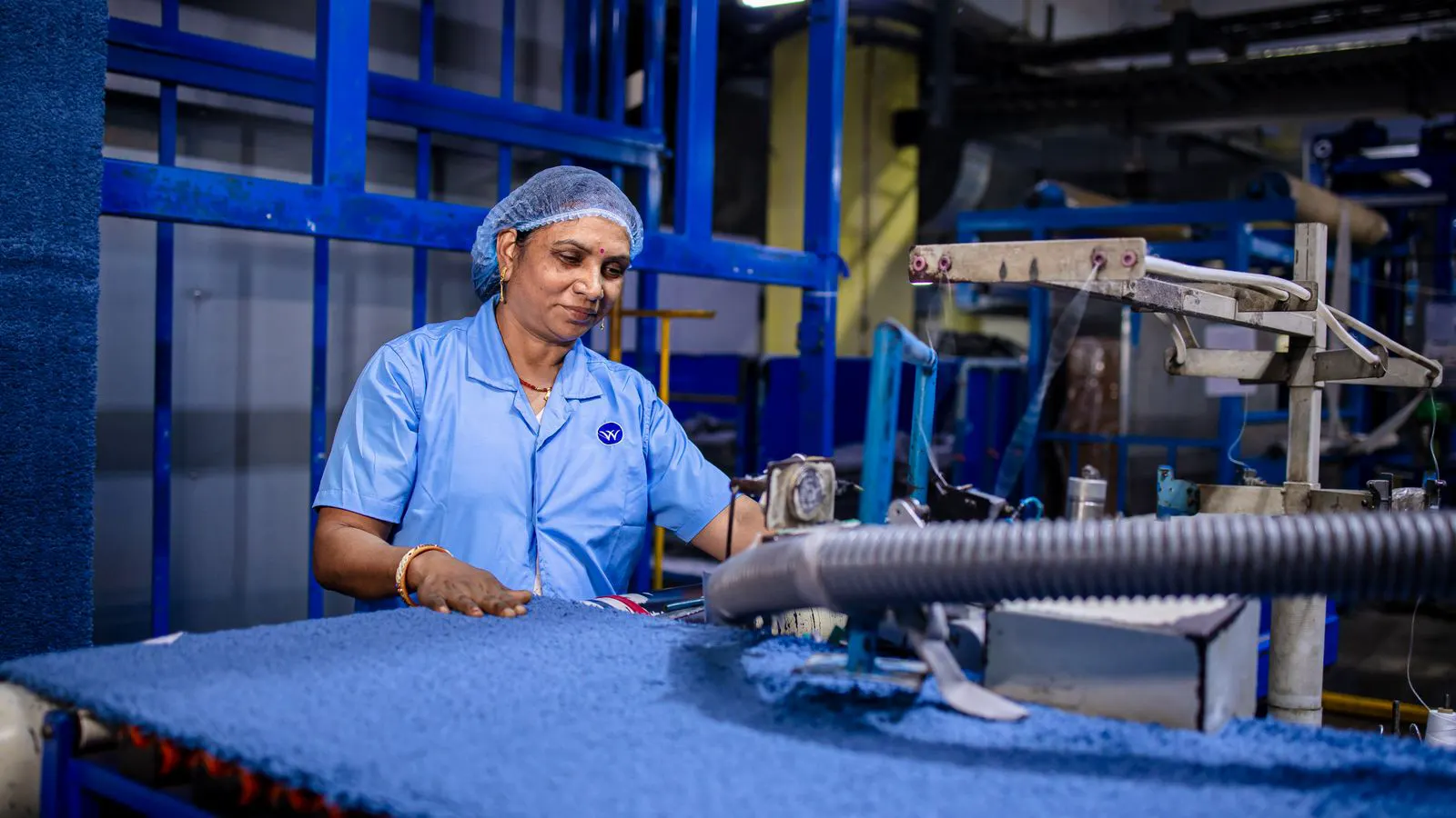
Proper vision system calibration aligns camera geometry, lighting, and sensitivity with fabric properties. This guide provides a step-by-step method for engineers to tune inspection systems, reducing false alarms and missed defects in textile quality control.
- Use a high contrast checkerboard or gray scale target to verify pixel-level geometric accuracy before testing live fabric.
- Adjust lighting angle and intensity to match the specific weave structure of the material being inspected.
- Set sensitivity thresholds based on the acceptable defect size for your specific production run, not the camera's maximum capability.
- Run a baseline verification pass with known good and known bad fabric samples after every major parameter change.
Why Calibration Fails Before Production Starts
Many textile inspection lines fail because the engineering team skips the alignment phase. The camera sees what the lens points at, but the software interprets that image through a set of assumptions. If the lens is tilted, the lighting is inconsistent, or the shutter speed does not match the line speed, the defect detection algorithm receives corrupted data.
Calibration is not a one-time setup. It is a continuous adjustment of the relationship between the physical fabric and the digital image. When you skip this step, the system either flags every weave variation as a defect or misses critical snags and holes. The goal is to make the digital representation of the fabric stable enough for the software to identify only the anomalies you care about.
Prerequisites for Accurate Tuning
Before touching any software settings, you need the right physical environment. The floor beneath the inspection unit must be level. A vibrating floor or a loose mounting bracket introduces micro-movements that the camera interprets as fabric motion.
Gather the following items:
- A high contrast checkerboard target or a gray scale card.
- A set of known defect samples (snags, holes, stains, and color breaks).
- A set of known good fabric samples of the same type and weight.
- A light meter to check illumination consistency.
- The camera manufacturer’s alignment tool or lens hood.
Ensure the camera lens is clean. Dust on the lens or the protective window creates static artifacts that look like small defects. Wipe the glass with a lint-free cloth and a specialized optical cleaner. Check the cabling for kinks or loose connections that might cause intermittent signal loss.
Step 1: Verify Mechanical Mounting and Lens Focus
The first step is physical. The camera must be mounted perpendicular to the fabric path. If the lens is angled, the image will be distorted, and the pixel dimensions will not match the real-world dimensions.
Use a laser level or a precision square to check the angle. Adjust the mounting bracket until the camera is parallel to the fabric surface. Lock the bracket bolts. Do not rely on temporary clamps.
Next, focus the lens. Use a macro target or a high contrast line pattern. Adjust the focus ring until the lines are sharp. Check the focus at the center of the field of view and at the edges. If the edges are soft, the lens may be out of alignment or the fabric may be moving out of the focal plane.
Reason: Geometric distortion and defocus cause the software to misinterpret fabric structure. A slightly blurred image makes it difficult for the algorithm to distinguish a true defect from a weave variation.
Step 2: Calibrate the Pixel-to-Real World Scale
Once the lens is focused, you must tell the software how many pixels equal one millimeter of fabric. This is the pixel-to-real world scale.
Place the checkerboard target on the fabric path. Capture a still image of the target. Use the software’s calibration tool to select the corners of the squares. The software will calculate the pixel dimensions of each square and compare it to the known physical size of the target.
If the scale is off, adjust the lens or the camera position. Re-capture the image until the software reports a scale error of near zero.
Reason: Defect size is critical for classification. A hole that is 2 millimeters wide is a different quality issue than one that is 10 millimeters wide. Without accurate scaling, the software cannot classify defects by severity.
Step 3: Optimize Lighting and Shutter Speed
Lighting is the most common source of false alarms. If the light is too bright, the image saturates, and you lose detail. If it is too dim, the image is noisy, and the algorithm struggles to see small defects.
Start with low intensity and increase the light until the fabric texture is clearly visible without clipping the highlights. Use a light meter to ensure the intensity is consistent across the entire width of the fabric.
Next, adjust the shutter speed. The shutter must be fast enough to freeze the fabric motion. If the fabric moves during the exposure, the image will be blurred. Start with a very short exposure and lengthen it until the image is clear.
Reason: Motion blur and inconsistent illumination are the primary causes of false positives. A stable, well-lit image is the foundation for accurate defect detection.
Step 4: Set the Background Subtraction and Threshold
With the image stable, you need to tell the software what a “normal” fabric looks like. This is the background model.
Run the inspection line with a roll of known good fabric. Let the software capture several images of this good fabric. The software will create a background model based on these images. This model represents the expected appearance of the material.
Next, set the threshold. This determines how much difference between the live image and the background model triggers an alarm. Start with a high threshold to minimize false alarms. Gradually lower the threshold until the system begins to flag known defect samples.
Reason: The background model adapts to the specific fabric type, weight, and color. The threshold balances sensitivity against noise. A threshold that is too low flags weave variations. A threshold that is too high misses small defects.
Step 5: Tune Sensitivity for Defect Class
Different defects require different detection logic. A hole is a lack of material. A snag is a disruption in the surface pattern. A stain is a change in color.
Create separate detection profiles for each defect class. For holes, the software looks for a dark area against a light background. For snags, it looks for a disruption in the texture pattern. For stains, it looks for a color shift.
Adjust the sensitivity for each profile independently. A hole detector can be more sensitive than a stain detector. A stain detector must be more sensitive than a color shift detector.
Reason: A single sensitivity setting cannot handle all defect types. Tuning each class separately allows you to optimize the detection rate for each specific quality issue.
Step 6: Run a Verification Pass with Known Defects
Before running the line at speed, you must verify the system with known defects.
Place the set of known defect samples on the fabric path. Run the inspection line at a slow speed. The software should flag each defect. Check the location of the flag against the actual location of the defect.
If the system misses a defect, lower the sensitivity for that defect class. If the system flags a defect too early or too late, check the synchronization between the camera and the fabric encoder.
Reason: This step confirms that the system is actually detecting the defects you care about. It also verifies that the flag location is accurate enough for the operator to identify the issue.
Common Mistakes to Avoid
- Ignoring fabric weight: Heavy, dense fabrics require different lighting angles than light, open weaves. Do not use the same lighting setup for a 120 GSM cotton and a 40 GSM silk.
- Skipping the gray scale check: Always verify the gray scale target to ensure the camera is not over or under-exposing the image.
- Using a single threshold: Do not use one sensitivity setting for all defect types. Each defect class needs its own profile.
- Neglecting the background model: If you change the fabric type, you must rebuild the background model. Do not reuse a model from a different fabric.
- Forgetting the lens hood: A lens hood prevents stray light from reflecting off the fabric into the lens. This is especially important for shiny or metallic threads.
Final Verification and Documentation
Once the system is tuned, run a final verification pass at production speed. Use a roll of good fabric and a roll with known defects. Check the false positive rate and the miss rate.
Document the settings. Record the lighting intensity, the shutter speed, the threshold values, and the background model version. Save this documentation in the equipment manual.
When you change the fabric type, refer to this documentation to see what settings worked before. This saves time and reduces the risk of errors during setup.
| Parameter | Typical Starting Point | Adjustment Goal |
|---|---|---|
| Lens Focus | Manual focus to center | Sharp image across full field of view |
| Pixel Scale | 1:1 with checkerboard | Error within 1% of real world size |
| Lighting Intensity | 50% of max | Clear texture without saturation |
| Shutter Speed | 1/2000th second | No motion blur at line speed |
| Threshold | 50% of max range | Detect known defects, ignore weave |
Conclusion
Calibration is a discipline, not a one-time task. It requires a steady hand, a clear understanding of the fabric, and a willingness to test. By following these steps, you can tune your vision system to provide reliable defect detection. This reduces waste, improves quality, and saves you from costly production stops.
Frequently asked questions
How often should I recalibrate the vision system?
Recalibrate after any major change, such as a new fabric type, a lens replacement, or a change in line speed. You should also run a verification pass weekly to check for drift.
Can I use the same calibration for different fabric weights?
No. Different weights and weave structures require different lighting angles and threshold settings. Always rebuild the background model when you change the fabric.
What is the best way to test the system before production?
Use a set of known defect samples. Run the line at a slow speed and verify that the system flags each defect at the correct location.
How do I reduce false alarms?
Start with a high threshold and lower it gradually until the system begins to flag known defects. Also, ensure the lighting is consistent and the background model is up to date.
What happens if the camera is not level?
The image will be distorted, and the pixel-to-real world scale will be inaccurate. This causes the system to misclassify defect sizes and locations.