Checklist: Pre-Installation Electrical Requirements for Looms
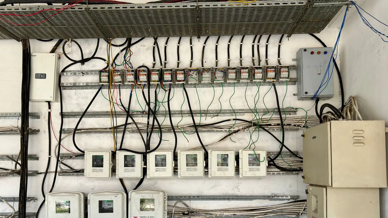
This audit checklist helps site engineers verify power capacity, wiring, and grounding before installing new looms. It covers factory electrical planning requirements to prevent tripped breakers, motor damage, and production delays during commissioning.
- Confirm single-phase or three-phase power matches the loom main drive before energizing the unit.
- Check main disconnects, breakers, and contactors for correct ampere ratings to prevent thermal overload.
- Verify grounding and earth leakage protection to protect operators and sensitive electronics.
- Inspect conduit, cable trays, and cable routing to avoid mechanical damage and heat buildup.
- Review the factory electrical planning layout for load balancing across the production floor.
Power Source and Load Verification
The first failure point for any new textile machine is often the utility supply. Before the loom arrives on the floor, the site engineer must match the machine datasheet against the available grid capacity. A mismatch here causes immediate nuisance trips or, worse, insulation breakdown on the main drive motor.
Start with the voltage and phase configuration. Many modern automatic looms require three-phase power, while smaller or older units may run on single-phase. Confirm the nominal voltage, such as 400V or 230V, and the frequency, usually 50Hz or 60Hz. Do not assume the factory supply matches the machine specification.
Next, calculate the demand load. The nameplate data usually lists the rated power, but it does not always account for the starting current of the main drive and auxiliary motors. For electric looms, the main drive motor often requires a starting current significantly higher than the running current. The supply transformer and main distribution board must handle this surge without dropping voltage on adjacent equipment.
Checklist: Power Source Verification
- Confirm Phase and Voltage: Verify the available supply matches the loom nameplate exactly. Record the actual voltage at the point of installation, not just at the main switchboard.
- Calculate Total Connected Load: Sum the rated power of the main drive, auxiliary motors, and control panels. Add a safety margin for future expansion.
- Check Transformer Capacity: Ensure the factory transformer has sufficient kVA headroom to support the new loom without overloading existing circuits.
- Verify Frequency: Confirm the grid frequency matches the machine requirement. Mismatched frequencies affect motor speed and heat generation.
Red flags to watch for:
- Voltage drop exceeding 5 percent under load.
- Main breaker rated significantly below the sum of connected loads.
- Transformer operating consistently near full capacity.
- Unexplained trips on adjacent machinery when the loom starts.
Distribution Board and Protection Devices
The distribution board is the heart of the loom electrical installation checklist. It houses the breakers, contactors, and relays that protect the machine and the factory grid. A poorly sized distribution board is a common cause of premature motor burnout.
Inspect the main disconnect switch. It must be clearly identified and rated for the total current draw. Check the main circuit breaker. It should be an inverse time curve type to allow brief inrush currents without tripping, while still protecting against sustained overloads.
The contactors controlling the main drive and auxiliary motors must be sized for the motor full load current. An undersized contactor will weld the contacts closed or open, causing sudden machine stops. Look for the magnetic trip setting on the overload relays. These should be adjustable and set to 95 to 105 percent of the motor full load current.
Checklist: Distribution Board Inspection
- Main Disconnect Rating: Verify the disconnect switch current rating equals or exceeds the total load.
- Main Breaker Type: Confirm the breaker is inverse time, not instantaneous, to handle motor starting.
- Contactor Sizing: Check contactor ratings against the motor nameplate current.
- Overload Relay Settings: Ensure trip settings are adjusted for the specific motor, not left at factory defaults.
- Circuit Identification: Confirm all circuits are labeled with circuit numbers and load descriptions.
Red flags to watch for:
- Burnt or discolored terminals on breakers or contactors.
- Missing or faded circuit labels.
- Overload relays set to maximum trip values.
- Lack of a dedicated earthing bar within the board.
Wiring, Conduit, and Cable Trays
Wiring quality determines the lifespan of the loom electrical system. Poor cable routing leads to insulation damage, which causes intermittent faults that are difficult to diagnose. Use the factory electrical planning drawings to map the cable path from the distribution board to the loom.
For low voltage control wiring, use insulated cables within conduit. For high voltage power cables, use flexible cables or rigid conduit depending on the environment. In textile mills, the air is often humid and filled with lint. Lint accumulation on hot conductors increases fire risk and degrades insulation. Ensure all conduit entries are sealed and cable glands are properly tightened.
Check the cable gauge. The conductor size must handle the continuous current without exceeding the thermal limit. A common mistake is using the minimum gauge allowed by code, leaving no margin for ambient temperature variations. In a hot factory, the allowable current drops. If the cable is rated for 30A at 30C but the ambient is 45C, the derating factor must be applied.
Checklist: Wiring and Routing
- Cable Gauge Verification: Confirm conductor size matches the calculated load and ambient conditions.
- Conduit Condition: Inspect conduit for cracks, sharp bends, and proper sealing at entry points.
- Cable Tray Load: Ensure the weight of the cables does not exceed the structural limit of the tray.
- Separation from Power: Keep control cables at least 150mm away from high voltage power cables to prevent interference.
- Mechanical Protection: Install cable guards where cables pass through high traffic areas or near moving parts.
Red flags to watch for:
- Cables resting directly on the floor or on hot surfaces.
- Sharp bends in conduit that damage the cable insulation.
- Exposed cable ends without proper terminations.
- Control and power cables bundled together in the same tray.
Grounding and Safety Protection
Grounding is the first line of defense against electrical shock and equipment damage. For textile machinery, the grounding system must be low impedance to allow fault current to flow quickly and trip the protection device. The loom frame, control enclosure, and cable shields must all be bonded to the main earth.
Check the earth leakage protection device, often called an RCD or GFCI. These devices detect current imbalance between the phase and neutral conductors. A trip in an RCD indicates a fault to earth, such as a damaged cable insulation contacting the machine frame. Set the RCD to 30mA for personal protection.
Verify the continuity of the earth path. Use a multimeter to measure the resistance between the loom frame and the main earth bar. The reading should be well below 1 ohm. High resistance indicates a loose connection or corroded terminal.
Checklist: Grounding and Safety
- Frame Bonding: Ensure all metal parts of the loom are connected to the earth busbar.
- Earth Continuity Test: Measure resistance from the frame to the main earth bar.
- RCD Function: Test the RCD trip mechanism with a test button.
- Shield Grounding: Confirm cable shields are grounded at the distribution board end.
- Isolation Verification: Check that the control system isolates from the main supply during maintenance.
Red flags to watch for:
- Rust or oxidation on earth connection points.
- Loose lugs on the earth bar.
- RCD tripping intermittently without a clear fault.
- Missing earth pins on the control panel.
Commissioning and Load Testing
The final phase of the loom electrical installation checklist involves energizing the system and testing under load. Do not skip the step of checking polarity. For three-phase systems, incorrect phase sequence can cause the main drive motor to rotate in reverse. This can damage the clutch, belt, or gear train.
Start with the control system. Power up the HMI or PLC and verify all inputs and outputs are responding correctly. Test the emergency stop circuit. The e-stop must cut power to the main drive immediately and lock out the control system.
Run the loom at no load first. Listen for abnormal noise from the main drive and auxiliary motors. Check the amperage draw with a clamp meter. It should match the nameplate rating. If the draw is higher than expected, check the mechanical alignment. A misaligned belt or worn bearing increases electrical load.
Checklist: Commissioning
- Phase Sequence Check: Use a phase meter to verify the correct phase rotation.
- Control System Test: Verify all HMI inputs, outputs, and alarms function correctly.
- Emergency Stop Test: Confirm the e-stop cuts power and locks the drive.
- No Load Run: Run the loom without threads and monitor amperage.
- Load Run: Run the loom with threads and verify stable operation.
Red flags to watch for:
- Motor running in reverse.
- Amperage fluctuating wildly during no load run.
- Unusual vibration or noise from the drive unit.
- Control panel alarms that do not clear after reset.
Factory Electrical Planning and Load Balancing
Installing a single loom is easier than integrating it into an existing production floor. The factory electrical planning must account for the load distribution across the entire building. Adding a large loom to one side of the floor can create voltage imbalance if the three-phase supply is not balanced.
Review the existing load schedule. Identify the circuits feeding the new loom. If the existing circuits are already heavily loaded, adding the loom will cause voltage drops on other machines. This can affect the performance of sensitive equipment, such as automatic threaders or computerized control systems.
Consider the location of the new loom relative to the main distribution board. Long cable runs increase impedance and voltage drop. If the loom must be placed far from the board, consider installing a local distribution panel to reduce the cable length. This also makes maintenance easier and reduces the risk of cable damage.
Checklist: Factory Electrical Planning
- Load Schedule Review: Verify the existing load on the target circuit.
- Phase Balancing: Ensure the new loom load is balanced across the three phases.
- Cable Run Length: Minimize cable distance from the distribution board to the loom.
- Local Distribution: Evaluate the need for a local sub-panel if the run is long.
- Future Expansion: Reserve capacity in the main board for additional looms.
Red flags to watch for:
- Significant voltage drop on adjacent machines when the loom starts.
- Uneven current draw across the three phases.
- Overheating at the main distribution board terminals.
- Lack of spare capacity in the main breaker.
Documentation and Handover
A complete loom electrical installation checklist is only as good as the documentation that accompanies it. The site engineer must provide a copy of the as-built drawings, cable schedule, and test results to the operations team. This record is vital for future maintenance and troubleshooting.
Include the electrical test report. This document records the phase sequence, earth continuity, insulation resistance, and amperage draw during commissioning. Keep it with the machine’s maintenance manual. If a fault occurs six months later, the baseline data helps the technician isolate the issue quickly.
The handover meeting should cover the location of the main disconnect, the RCD trip procedure, and the phase sequence. Train the operator on how to perform a basic electrical safety check before starting the machine. A simple visual inspection of the control panel and cable routing can prevent many common issues.
Checklist: Documentation and Handover
- As-Built Drawings: Provide updated electrical schematics showing the loom connection.
- Cable Schedule: List all cable types, gauges, and routes.
- Test Report: Include phase, earth, and amperage test results.
- Operator Training: Demonstrate the main disconnect and RCD reset procedure.
- Maintenance Log: Start a log for electrical inspections and faults.
Red flags to watch for:
- Missing cable schedule or as-built drawings.
- Test report not signed by the electrical engineer.
- Operator unfamiliar with the location of the main disconnect.
- No record of the commissioning date or test results.
Frequently asked questions
What is the typical voltage requirement for a modern automatic loom?
Most modern automatic looms require three-phase power at 400V or 230V, depending on the region and manufacturer. Always verify the specific model in the technical datasheet.
How do I check if the factory transformer can handle a new loom?
Calculate the total connected load of all machines on the transformer. If the new loom pushes the load beyond 80 to 85 percent of the transformer capacity, you may need to upgrade the transformer or add a separate feed.
Can I use single-phase power for a three-phase loom?
No. Using a single-phase supply for a three-phase motor will cause the motor to overheat and fail quickly. You must provide the correct three-phase power or use a phase converter if single-phase is the only option, though this is not recommended for heavy industrial loads.
What is the purpose of the RCD in a loom electrical system?
The RCD, or residual current device, detects current leakage to earth and trips the circuit. It protects operators from electric shock and detects insulation faults in the loom cables.
How often should I inspect the loom electrical installation?
Perform a visual inspection monthly for dust, lint, and cable damage. Conduct a full electrical audit, including insulation resistance and earth continuity tests, at least once a year or after any major maintenance.